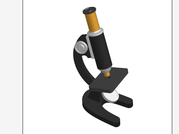
The microscopes is a symbol of our civilization. Throughout this tutorial on how to illustrate a vector microscope you’ll take advantage of numerous Illustrator tools. You will learn how to use blends, art brushes and 3D rendering in Adobe Illustrator. Let’s get started!
Step 1
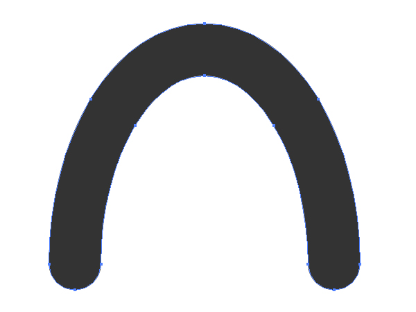
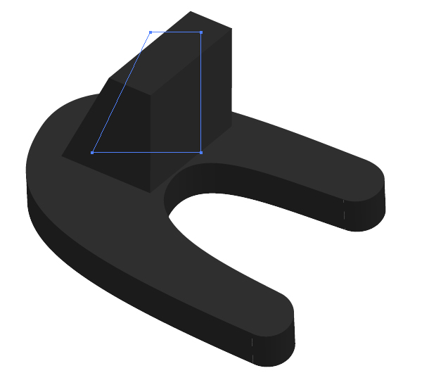
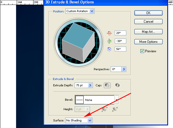
First, create a horseshoe shaped path, filled with dark color.
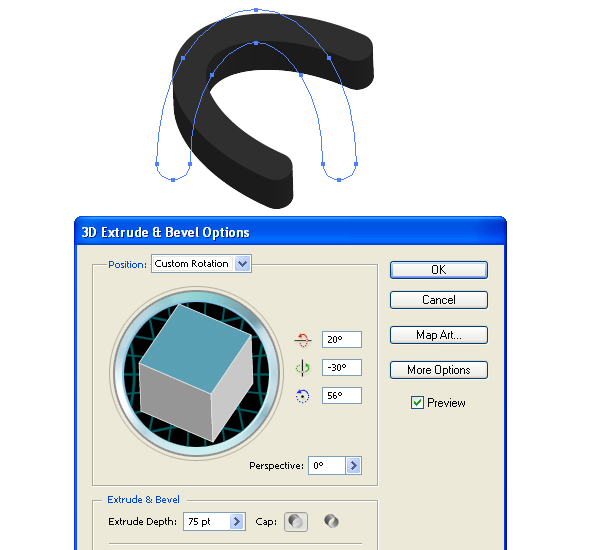
Go to Effect > 3D > Extrude & Bevel, and set there the values shown below. Your result is a support detail of the microscope.
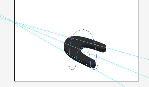
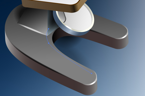
Now you need to grab the Direct Selection Tool (A) and change the form in order to comply with the perspective demands. See the diagram below for reference.
Step 2
Illustrate the second part of the support detail the same way.
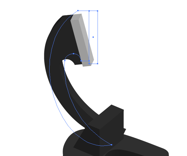
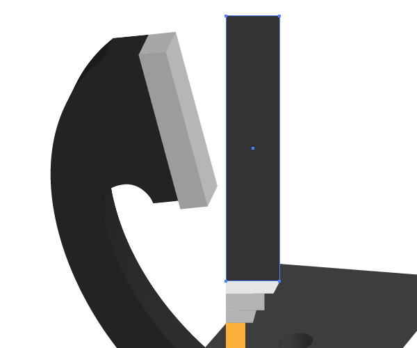
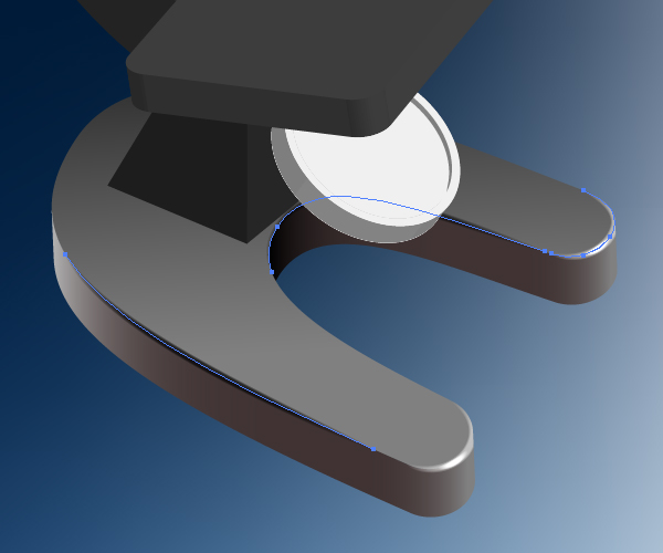
Sketch the next support of the microscope, which consists of two shown paths.
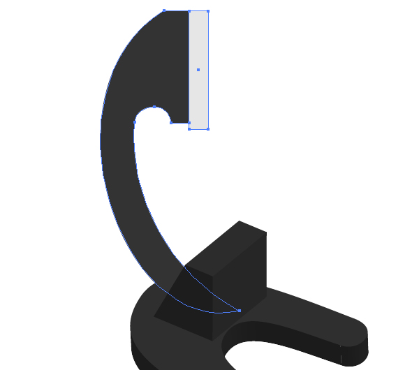
Group them by going to Object > Group (Command + G), and apply the 3D extruding to this group.
Step 3
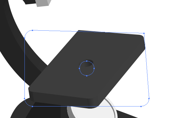
Draw the path that will represent a mirror in the lower part of the microscope.
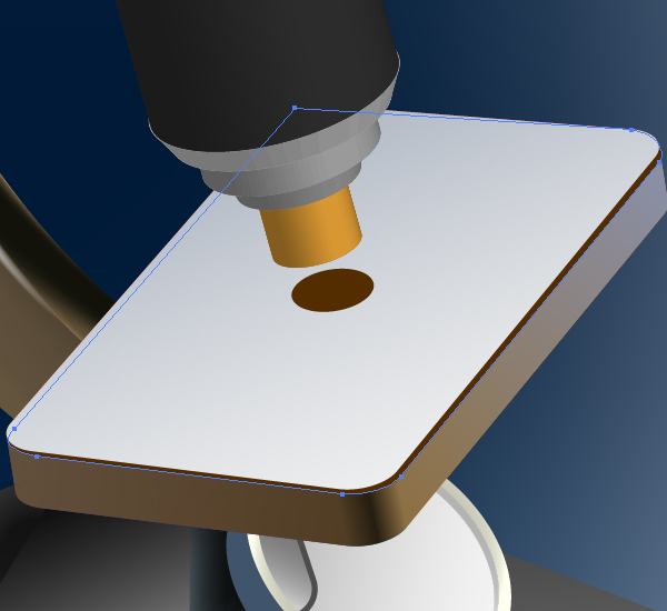
Illustrate the table using the Compound path. Pay attention to the asymmetrical shape of the table. You need to achieve this in order to meet the requirements of the perspective too.
Step 4
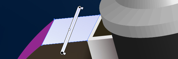
Make now the following paths touching with one another.
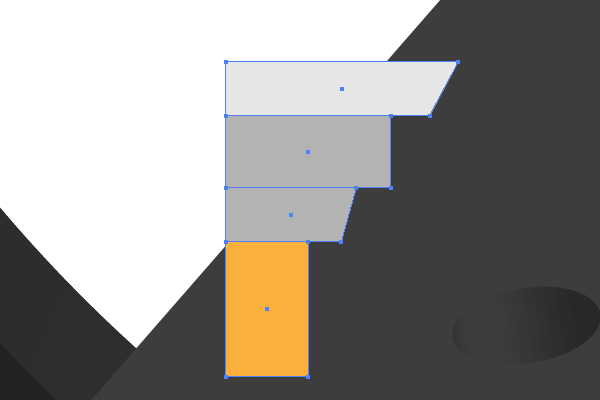
Place an elongated vertical rectangular path over them as shown below.
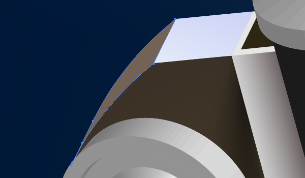
Create the following paths also.
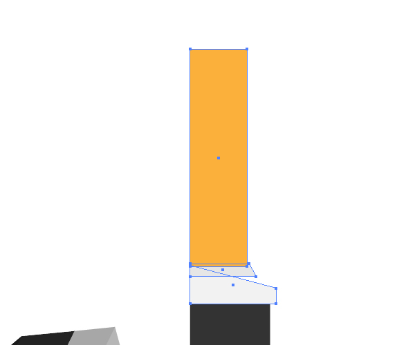
And draw the last path as shown.

After that group all the paths,…
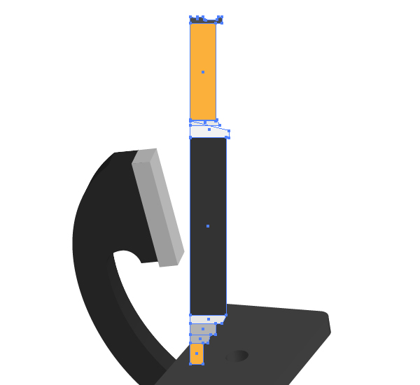
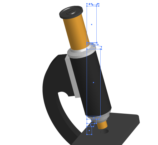
…and go to Effect > 3D > Revolve and set there the values shown below.
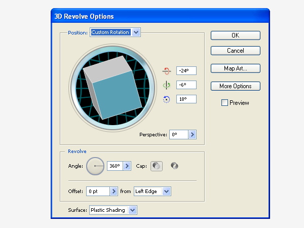
The result should look like the image shown.
Step 5
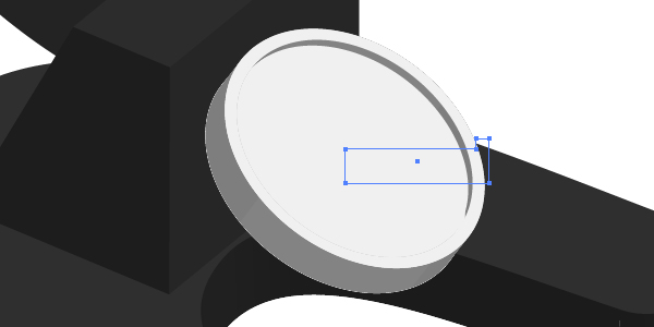
Produce the detail of tuning the microscope using 3D revolving.
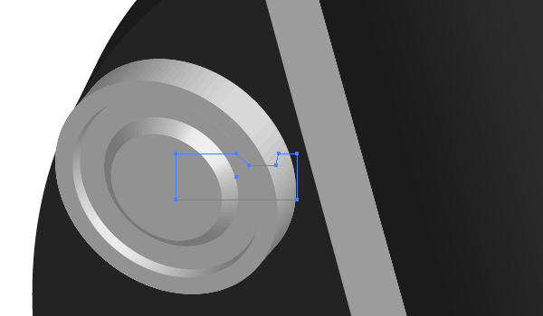
You need to achieve the following result.
Step 6
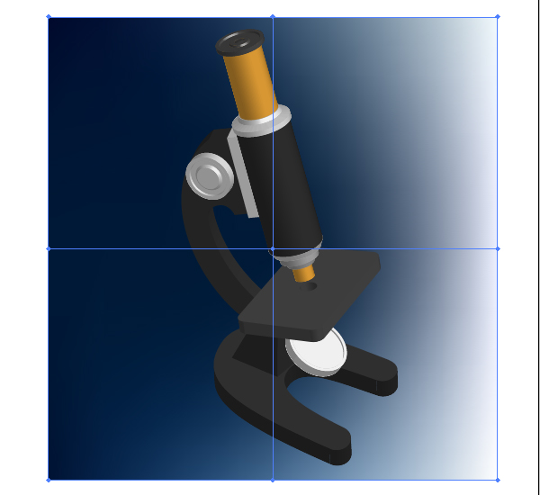
Paint now a background using the Mesh Tool (U) as you can see it in the diagram below. Bear in mind that you must create a background before coloring the microscope, because the background affects the luminosity of the objects. Let a source of light be placed on the right side.
Step 7
Select the horseshoe shaped path,…
…go to the Appearance palette and click there the reference to 3D Extrude & Bevel in order to edit effect.
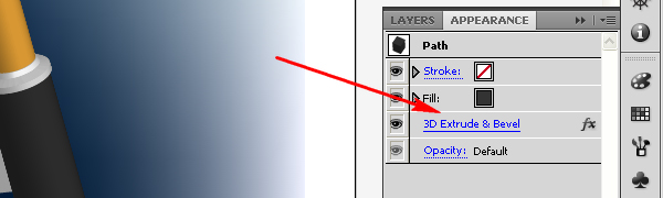
Specify a rendering style of the surface to No Shading. You need to do this in order to decrease the quantity of paths after the expanding.
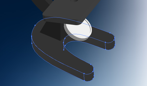
Now go to Object > Expand Appearance. And apply Object > Ungroup three times.
Step 8
Unite the lateral parts (selected in the diagram below) by going to the Pathfinder palette.
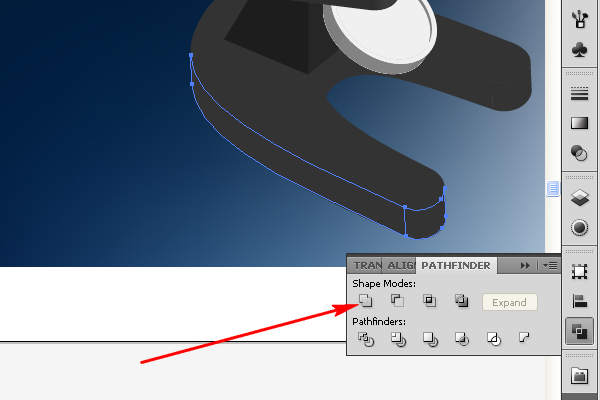
Also unite the following paths too.
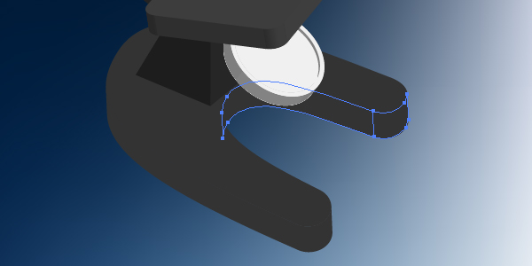
After that you must have three paths only (they are filled with different colors for your convenience).
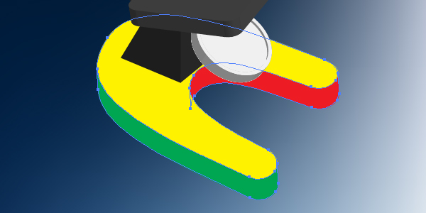
Step 9
Select now the green path and fill it with the linear gradient shown.
Fill the red path with the linear gradient too.
The yellow path should be filled with an angled gradient.
Step 10
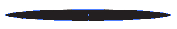
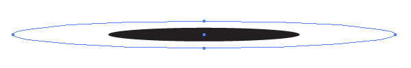
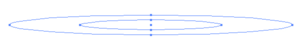
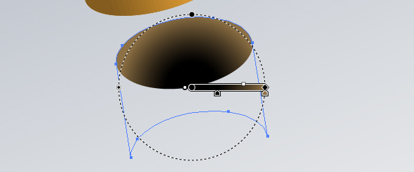
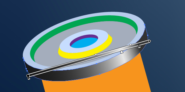
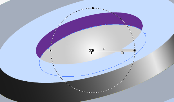
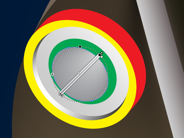
Grab the Ellipse Tool (L) and draw an elongated elliptical path. Fill it with black.
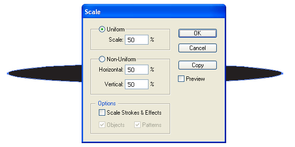
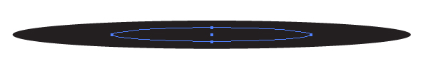
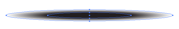
Copy it and paste in front (Command + C then Command + F). Then go to Object > Transform > Scale and set there the values shown below.
And after these manipulations you will achieve the following result.
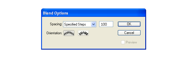
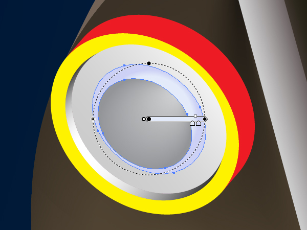
Go to Object > Blend > Blend Options and set the Spacing to Specified Steps and the quantity of steps to 100.
Change the Opacity of the biggest ellipse to 0.
Select both elliptical paths and go to Object > Blend > Make (Command + Alt / Option + B).
Step 11
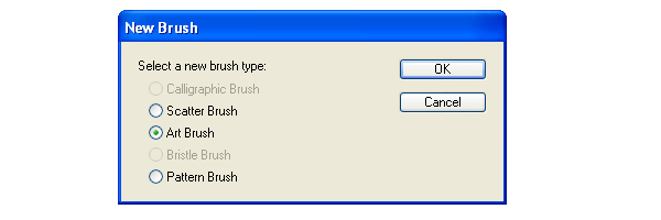
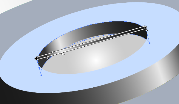
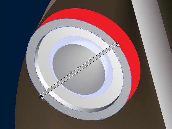
Drag and drop this path into the Brushes palette. Select the Art Brush option in the dialog box.
Set the items for the brush as you can see them in the diagram below. Name this brush “Black brush.”
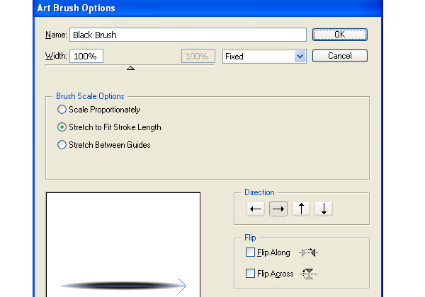
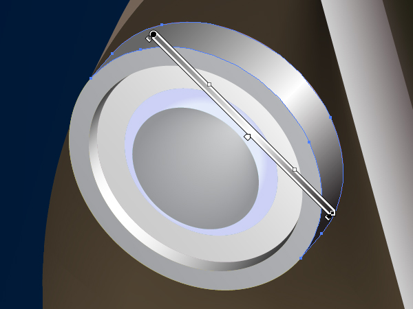
Produce the “White brush” where the ellipses are filled with white the same way.
Step 12
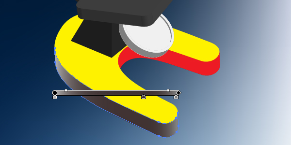
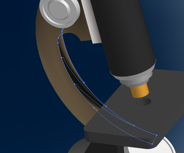
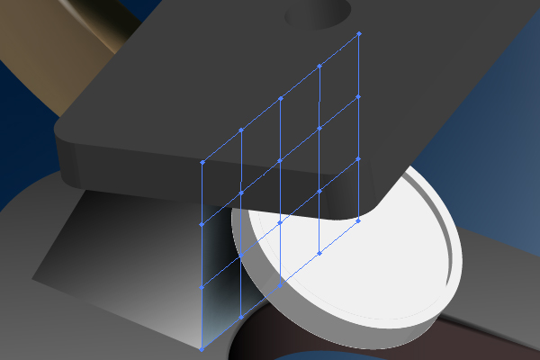
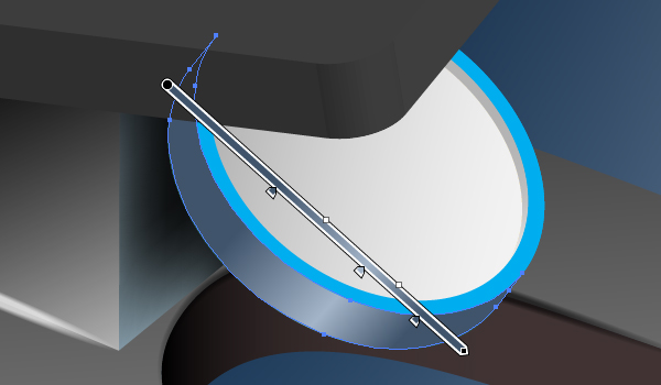
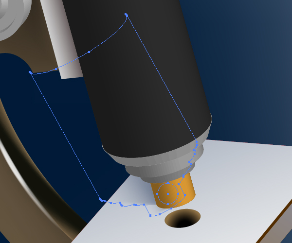
Take the Pen Tool (P), illustrate a path in the support part of the microscope (shown in the diagram below) and apply the “White brush” to it.
Change the Stroke weight and the opacity of this path.

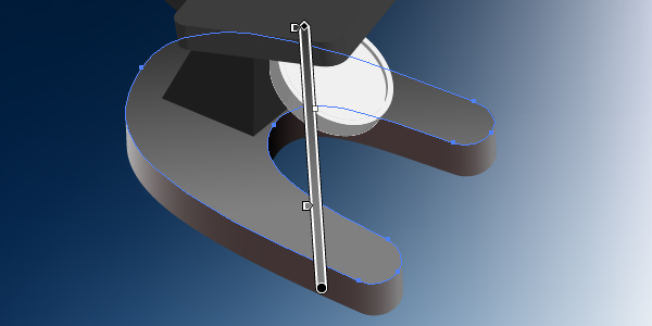
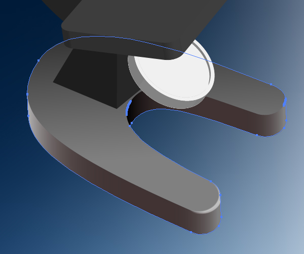
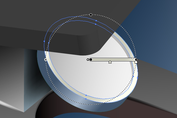
Now select the group of the support detail (see the diagram below for reference), copy it and paste in front (Command + C then Command + F). Unite three paths of it by going to the Pathfinder palette, and place the received path in the top of the Layers palette. Select these both paths and go to Object > Clipping Mask > Make (Command + 7).
Step 13
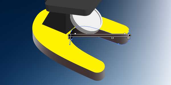
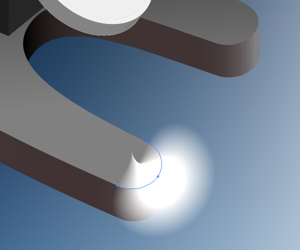
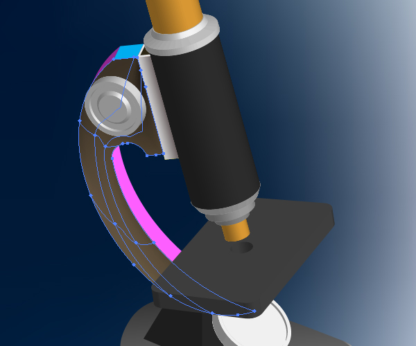
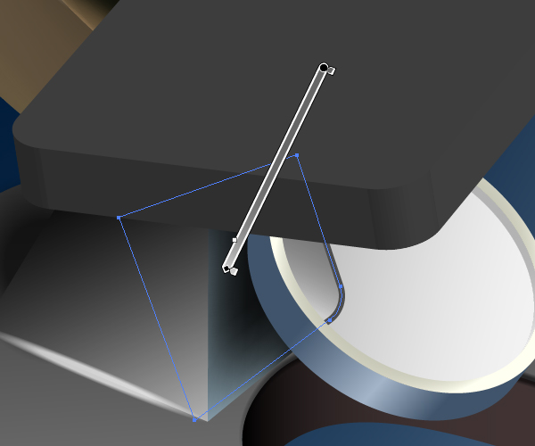
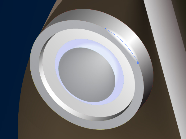
Illustrate the next path using the Pen Tool (P) over one which has just been created and apply the “White brush” to it too. Do not decrease the opacity of this new path, in order to represent a light spot on the support detail.
Apply then Black and White brushes for the following paths on the support detail.
Step 14
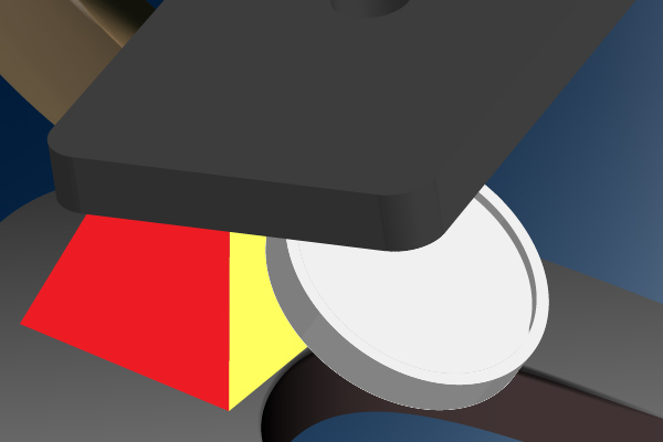
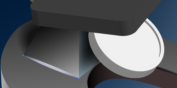
Expand the next support of the microscope, as you did it in Step 7.
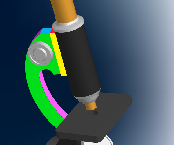
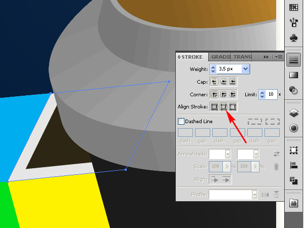
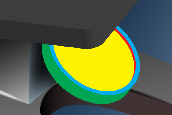
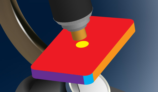
Select the red path and change the Fill and the Stroke colors. Go to the Stroke palette and align the Stroke to inside.
Fill the yellow path with an angled linear gradient.
After that convert the green path into the mesh and change the colors of nodes using the Mesh Tool (U).
Fill the blue path with an angled gradient.
Fill the violet path with light brown.
Create the mesh from the pink path. See the diagram below.
Step 15
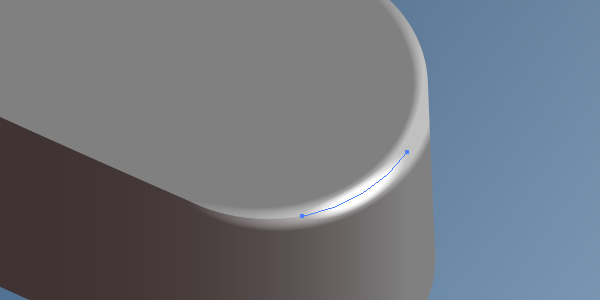
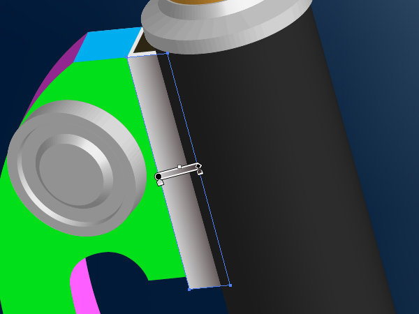
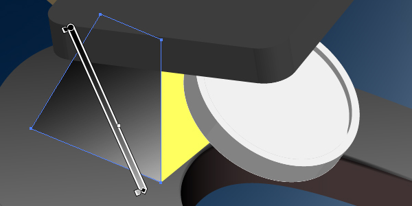
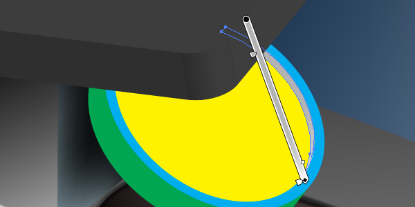
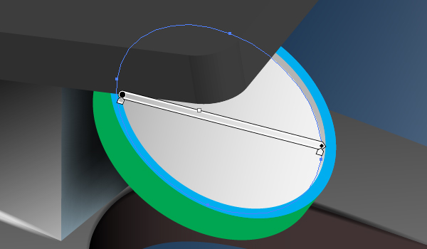
Make a light spot on the detail by using the “White brush.”
Step 16
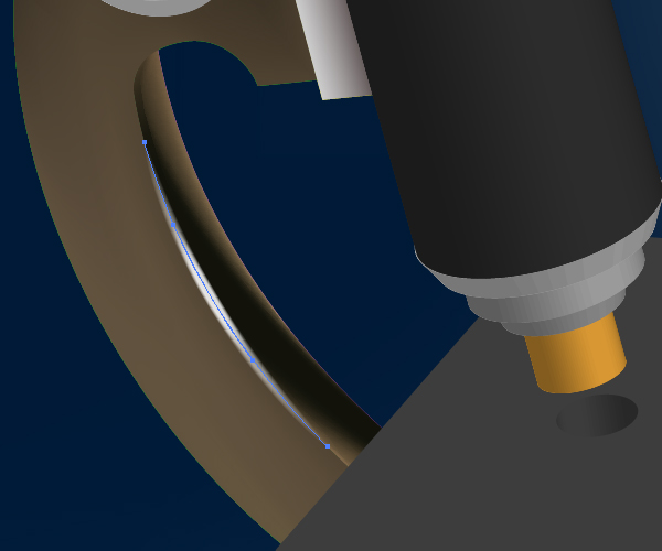
Expand the detail under the mirror.
Fill the left part of the detail with an angled gradient.
And create a mesh from the right part of the detail. Change the colors of nodes in order to reproduce the light distribution. Give heed to a shadow from the mirror.
Create a shadow from the detail itself by applying the “Black brush.”

Produce a light spot the same way.
Step 17
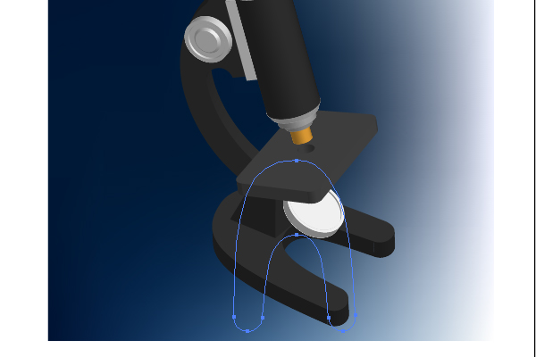
Now expand the mirror.
Fill the red path with a linear gradient.
Fill the yellow path with the linear gradient too.
The green path should be filled with an angled gradient.
You may fill the blue Compound path with the Radial gradient.
The mirror must reflect the bottom of the table. Create this reflection using the angled linear gradient. You should have a picture the same as below.
Draw a light spot on the mirror using the technique described above.

Step 18
Expand the table now.
Fill the orange path with an angled gradient. Keep in mind the color-value of the 1st color-stop of the gradient (pointed by an arrow on the diagram).
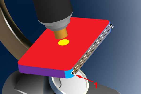
Repeat these manipulations with the violet path. But now keep in mind the color-value of the 2nd color-stop of the gradient (pointed by an arrow on the diagram).
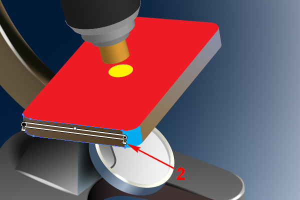
Fill the blue path with the linear gradient that goes from the 2nd color-stop to the 1st color-stop. You should do this in order to represent a flow of colors.
Fill the yellow Compound path with an angled gradient.
Copy this Compound path and paste it in back (Command + C Then Command + B). Move it slightly downward and fill it with brown.
Fill the hole in the table with a radial gradient.
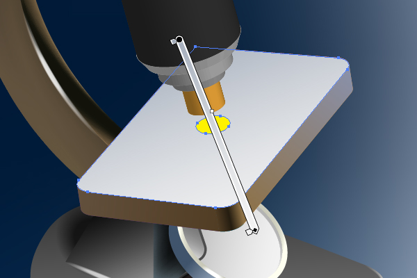
Use a blend for creating the shadow from the central tube of the microscope. Do it by yourself without assistance. You already know how to create blends (see the diagram below).
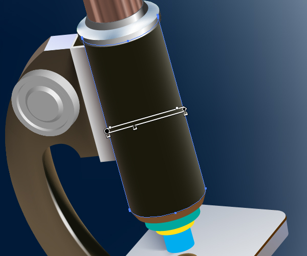
Step 19
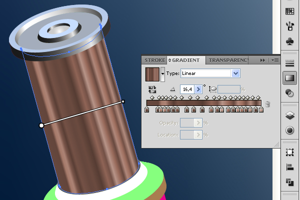
Expand the central tube of the microscope.
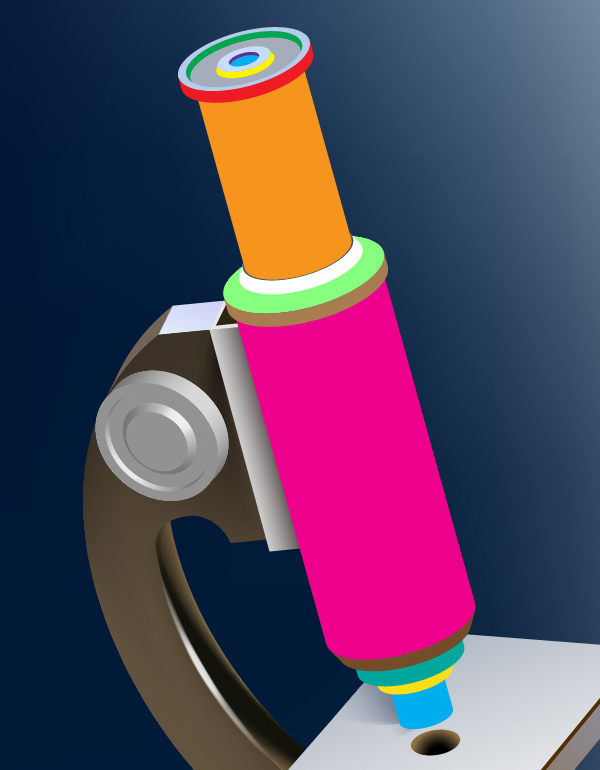
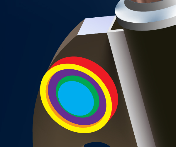
Fill the red path of the microscope eye-piece with an angled linear gradient.
Fill the following Compound paths of the eye-piece with usual colors.
Fill the yellow path with an angled gradient too.
Repeat these manipulations with the green path as shown
The blue path must be filled with the Radial gradient.
Specify the distribution of light in the violet path using the linear gradient as shown.
Use the usual color for filling the inner Compound path of the eye-piece.
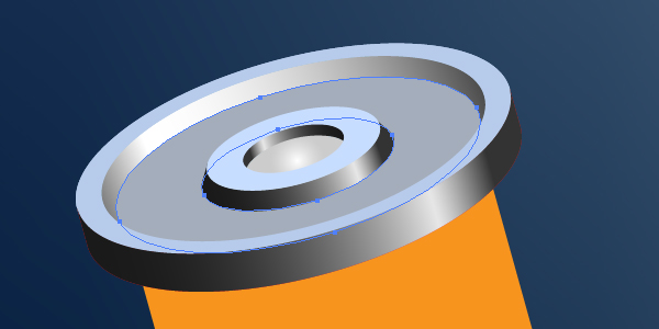
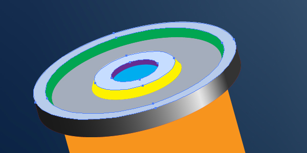
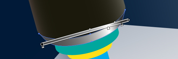
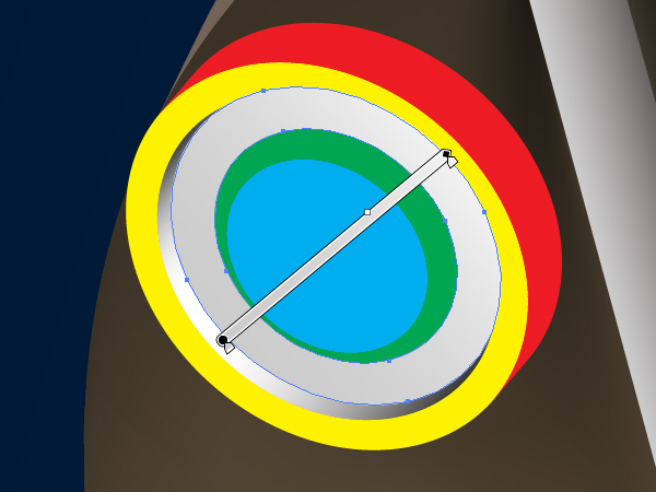
Step 20
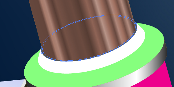
Fill the orange path in the top part of the central tube of the microscope with the following linear gradient.
Use the usual gradient for filling the light brown path.
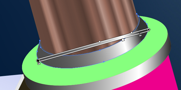
Fill the ring of the tube with dark gray.
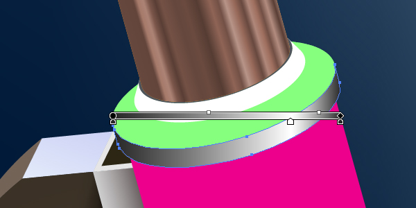
The white path must be painted using the linear gradient also.
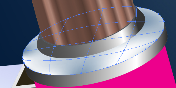
Convert the green path into the mesh and change the node colors by applying the Mesh Tool (U). Follow the diagram shown below.
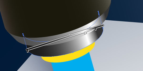
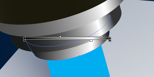
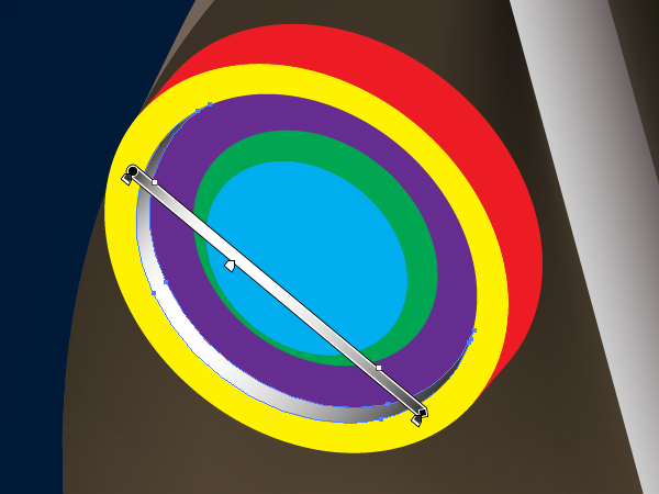
Step 21
The residuary paths must be filled with gradients too. See the images below for reference.
Step 22
Expand the tuning detail.
Fill the paths as shown in the diagrams below.
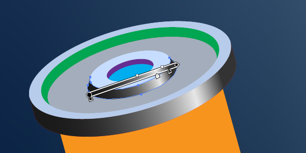
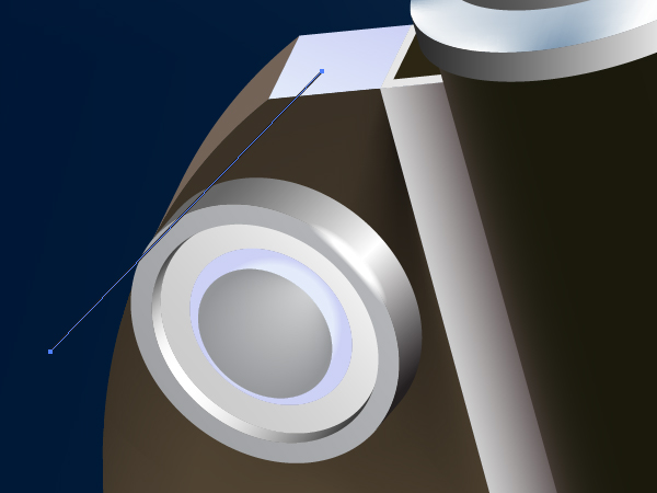
Apply the “White brush” to the path shown below.
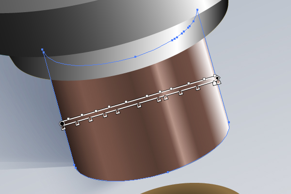
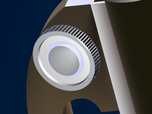
Step 23
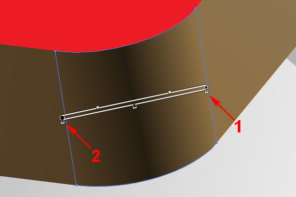
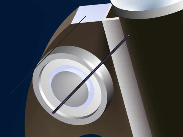
Let’s illustrate the notches on the lateral surface of the tuning detail. First draw a thin black line using the Pen Tool (P).
Copy it and paste in front (Command + C then Command + F), move it, and increase the Stroke weight in order to receive a thick line.
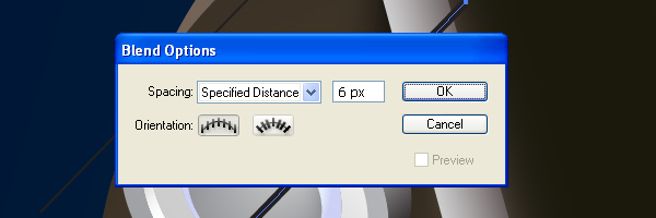
Go to Object > Blend > Blend Options and set the items which you can see in the diagram below.
Select both paths and go to Object > Blend > Make (Command + Alt + B).
Step 24
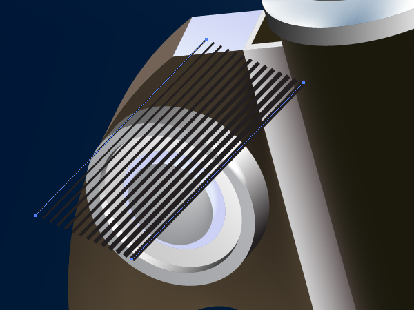
Create an analogous blend.
And crop these blends with the Clipping mask.
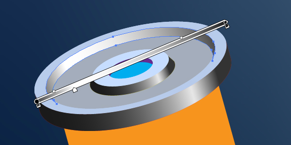
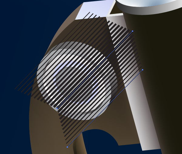
Step 25
Draw a shadow from the mirror by using the “Black brush.”
And illustrate a shadow from the support detail the same way.
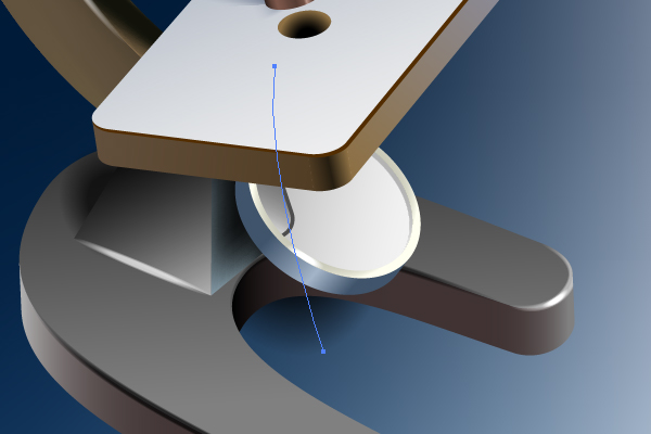
Step 26
You may now draw erythrocytes by using the 3D revolving effect. See the diagram below for reference.
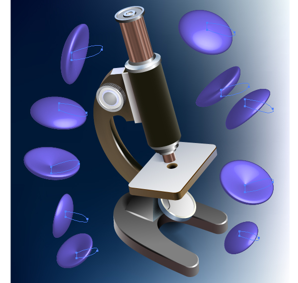
Produce the lines in the background with the aid of the blend.
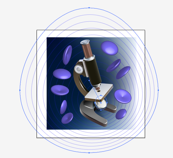
And crop them with the Clipping path.
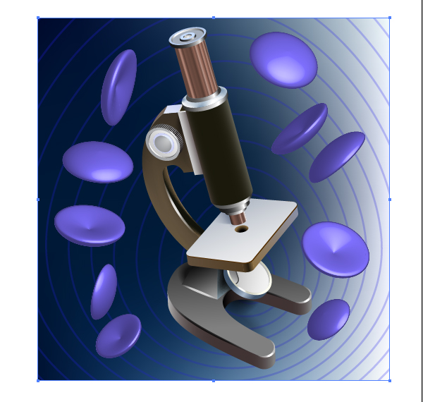
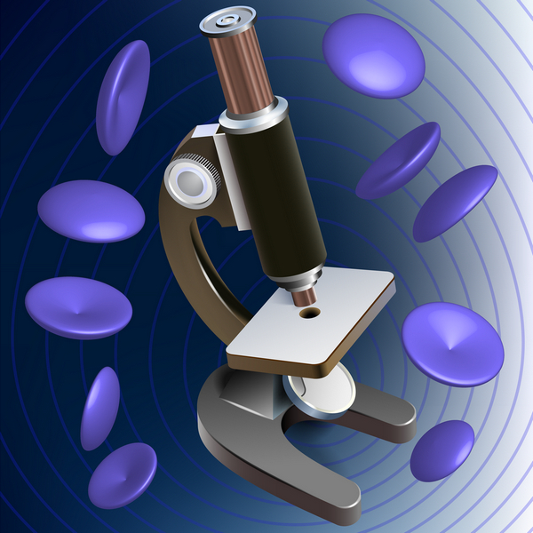
Conclusion
The final image is below. Every microscope is the exact scientific tool which allows you to watch the majesty in the microcosm.